

BIGREP BLADE – A SMART 3D SLICER FOR INDUSTRIAL APPLICATIONS
A New Standard in Large-Format 3D Slicer Software
BLADE, BigRep’s easy to use slicer software, allows for greater control of printing parameters on all BigRep large-format 3D printers. Its integrated estimation engine gives accurate printing time and material use predictions for unmatched planning and productivity. As one of the fastest and most precise slicers on the market, this cutting-edge software is optimized for industrial part slicing to make for a rapid, hassle-free start to printing.
Built on industry-standard software with key features and optimizations:
- Specially designed for BigRep 3D printers
- Range of options to reduce large-format print times and material use
- Frequently updated BigRep material presets for fast, quality prints
- Expert and basic UI modes for precision control and ease of use
- Accurate print time and material use predictions
- Automated batch production planning


3D PRINTING SIMPLIFIED.
BLADE’s user-friendly interface makes for a simplified printing experience. By optimizing for large-format parts and integrating presets for all BigRep-compatible materials, the BLADE slicer streamlines the industrial printing process to save users’ time and ensure successful, quality prints.
How to Use BLADE 3D Slicer Software
How to Use BLADE 3D Slicer Software
Requirements
- Windows 10 x64
- Memory: 8GB or more
- CPU: intel core i5 or better
- GPU: dedicated graphics card recommended, but works on integrated as well
First Steps
Blade is heavily based on Ultimaker Cura. In most cases, you will get far by referring to Cura documentation: https://support.ultimaker.com/hc/en-us/sections/360003548579-Getting-started
The following sections describe the differences and unique features of Blade in contrast to Cura.
The user may:
- Load geometries and manipulate them in preparation for printing
- Use preinstalled extensions for manipulating the model and the toolpath output
- Select setting presets for materials and printer for printing
- Change settings (basic/advanced/expert)
- Create gcode file and use it to print on a BigRep printer
The user may not:
- Customize Blade in a significant way, i.e.
- adjust any Blade files (files in the install directory or in the appdata directory)
- change machine settings (printer/extruder settings)
- add own printers
- add own materials
- Use experimental settings.
- Disable post-processing.
- Install plugins or materials from the Ultimaker Marketplace
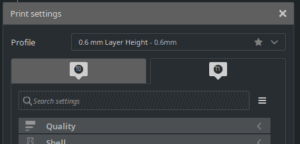
If you hold the cursor over a setting you get a description of the setting and its effect.
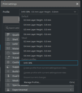
Intent Profiles:
- “Default” is faster than “Visual” and comparable with former “Medium” preset.
- “Visual” profiles will result in a longer printing time, but gives a higher overall print quality. Comparable with former “Quality” preset.
Visual intent profiles might not be available for all Material/Extruder/Machine combinations. More intent profiles might be added over time.
Z Seam Alignment:
- Here you can chose where Blade is placing the retraction points.
- In the case of standard settings, Blade will try to place retraction points at less visible positions. This is suitable for most geometries. However, in some rare cases you have to do manual adjustments.
- If you switch to “User Specified” you can choose a a X-Y coordinates as in Simplify3D. If you also check “Z Seam Relative” the position is relative the center of the model.
Gradual Infill:
- It changes the amount of infill gradually.
- This results in a lower infill of the main body and a higher infill closer to the surface of the part.
- This reduces the printing time and amount of material needed.
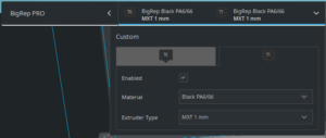
The extruder setup in Blade should be the same as on the machine. If there is more than one physical machine, then there shall be for each physical machine a virtual representative in Blade.
For example it is possible to add two ONEs with different extruder setups. These will be saved locally on the user’s computer and can not be easily transferred to another computer.
Extruders can be enabled and disabled by right clicking on the extruder in the extruder menu.

This is important as there are some setting that change if one or both extruders are enabled. For example: Mixed Mode/Sequential Printing will only function when only one extruder is enabled and Tandem Mode on the ONE can also just be activated with only one extruder.
As a difference compared to Blade 2.2.1 and below, extruders don’t need to be disabled to function properly with single extrusion, beside the fact, that you need to change support and adhesion extruder to the extruder you want to use.
When Blade is opened for the first time, you are asked to add a printer. Additional printers can be added later
- Click on your current printer’s name at the top left corner and then on “Add Printer”
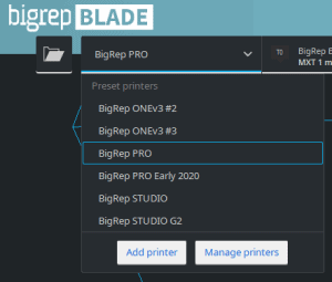
- You can also click on “Settings” in the menu bar and then on “Printer”, “Add Printer…”
- In the following menu you can add a printer and also change its name:
Custom Profiles
A custom profile saves changes to the current default settings.
A star next to the name of the profile indicates changed settings. You can save these changes into your own profile. Also the current layer height, from the current profile will be saved in this new profile, but can also be changed afterwards.
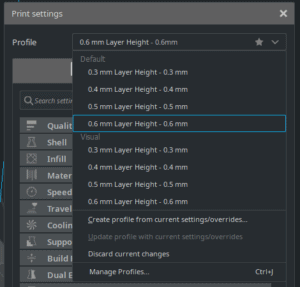
After the profile is saved, it is placed below the default profiles section. You can also update your custom profile with additional changes.
If you go to “Manage Profiles”, you can also see the changes you made. There are global and specific extruder settings.
These profiles are only available in your added machine and thus for all extruders and materials.
Profiles can also be exported and imported.
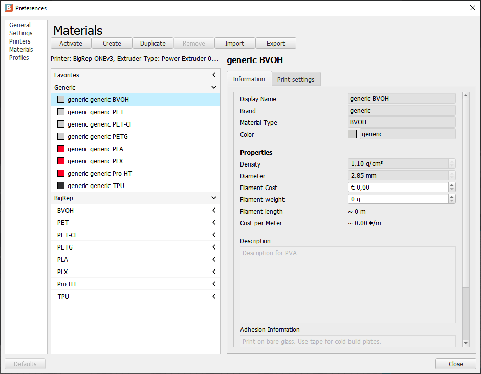
Custom Materials
If you want to add your own none BigRep material, you can do so by going to the manage material page (Material → Manage Materials…)
This window shows the generic materials on which the BigRep materials are based on. You can duplicate one of these files or create a new one. It is recommended to duplicate the material if you have one which is basically the same as one of our materials (a different kind of PLA for example). Please be aware that when you copy a material you also copy all settings. Some materials are not compatible to all extruders, this can not be changed!
When you have created your own material, you can change some settings, like the displayed name or brand, but also color, density (which is used for calculating the used material) and filament diameter (which is mostly 2.85 mm and used for calculating the right amount of extruded material).
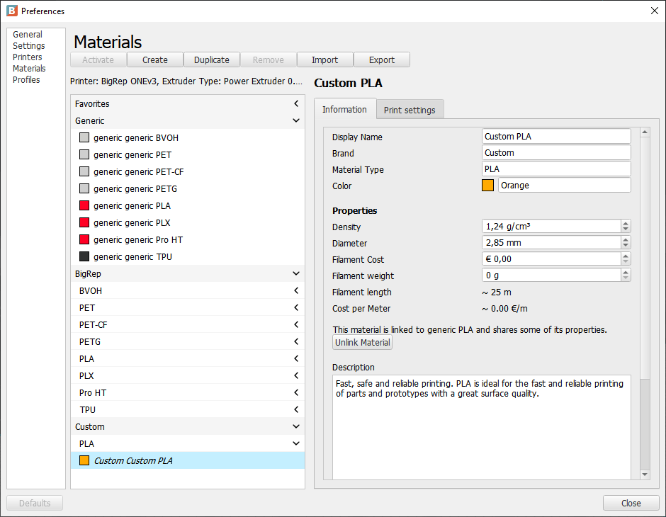
The current displayed print settings are the ones for the currently selected extruder and can be changed for each extruder separately (you have to close the window, change the extruder and than going back again, same for printers). Only a few material related settings can be changed here. If you want to change more settings you have to create a custom profile (see above).
Support Blocker
WHAT IT DOES
Support Blockers prevent support within their volume.
WHY IT SHOULD BE USED
Usually, support is placed on all surfaces with an angle higher than the support angle (overhang).
Sometimes this is not necessary and should be blocked, for example:
- Usually, small horizontal holes don’t need support and it can be hard to remove support there.
- Small surfaces which could be printed with bridging.
- Inside a model, where it can’t remove.
How to use Support Blocker
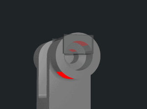
Firstly, it is necessary to load/import a model. The following icon (contained in the toolbar on the left) can be selected if the model is active:
![]()
Good to know:
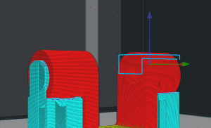
- Red surfaces on the model indicates an area where support will be placed.
- The Support Blockers can only be placed on the surface of the model.
- Each cube can be transformed/moved/scale as a normal model.
- To block the support the red surface must be within the cube/Support Blocker.
- Support Blocker and Custom Support can be placed in the same model.
Custom Support
WHAT IT DOES
Custom Support places support where it would not be placed by default.
WHY IT SHOULD BE USED
Usually, all surfaces which have a lower angle than the support angle will have no support.
Sometimes it’s necessary to place more support, for example:
- Ensure that small area support are sufficiently strong, especially if the piece is tall.
- Stabilize a model to make sure it doesn’t fall over.
How to use Custom Support
Firstly, it is necessary to load/import a model. When the model is active, the user can select in the toolbar on the left the following icon:

Good to know:
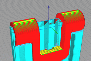
- Red surfaces on the model indicate areas where support will be placed.
- Custom Support can only be placed on the surface of the model.
- Each cube can be transformed and moved like a normal model.
- The support will be generated everywhere below up to the inside (upper surface) of the cube/Custom Support.
- Support will be always placed even when the support is deactivated.
- Support Blocker and Custom Support can be placed in the same model.
Both extruders must be enabled.
Dual extrusion with two or more models
- Each model can be mapped to one of the extruders.
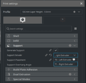
Dual extrusion with a different support extruder
- Make sure you have the right material mapped to the correct extruder.
- Also the model(s) should be connected to the extruder which is not used for support.
- Then the “Support Extruder” need to be changed to the other extruder.
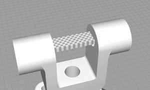
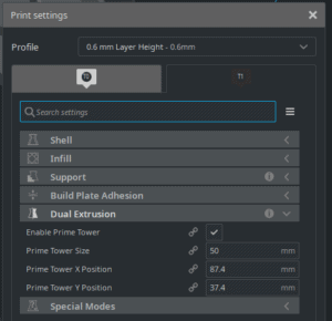
Prime Tower adjustments
- Independent of how the dual extrusion is used, the prime tower should be adjusted.
- Dependent of the height of the model, also the size of the tower needs to be adjusted to ensure it’s stability and preventing it falling over.
- To avoid oozing, the tower should be placed as near as possible to the model.
All at Once
WHAT IT DOES
All models will be printed at the same time. Called Layer-by-Layer in Simplify3D.
This means that the printer will print one layer of each model and than move to the next layer, and so on.
WHY IT SHOULD BE USED
All at Once is the default (if both extruders are enabled) and easier to use than “Mixed Mode”.
In particular, this configuration is safe and you can print any scenario without taking care about safety distances.
How to use “All at Once”
If the second extruder is enabled, “All at Once” is the only possible mode. In particular, you cannot change it.
Otherwise, you can change the mode in “Special Modes/Print Sequence”.
Good to know:
- “All at Once” is the default value if both extruders are enabled. Otherwise, “Mixed” is the default.
- It is easier to use than Mixed mode.
- A disadvantage is the following: In case of a printer failure, all prints will be lost.
- Printing results might be different for each model because the relative motions are different.
- Printing time might be higher because of more travel moves.
Mixed/Batch Printing
WHAT IT DOES
Mixed printing mode replaces the standard Cura “One at a Time”. Together with “Mixed” we offer the batch printing plugin (Menu→Extensions→Batch Printing) to get the full out if this mode.
To use the full potential of the print bed and still uses the advantage to print model by model the mixed mode combines layer by layer printing with model by model.
But instead of printing each model separate it uses row and columns to make the print safer.
Depending on the used printer the behavior is slightly different. The ONE and PRO starts at the front of the printer, while the STUDIO and STUDIO G2 start from the right.
WHY IT SHOULD BE USED
Mixed mode is more complex to use than “All at Once”.
The benefit is that the models will be printed as they would be printed alone. Whenever a model is finished it can’t be effected by a printer failure.
HOW TO USE MIXED MODE
“Mixed” will be automatically enabled when you disable the second extruder.
You can alter the mode via “Print Sequence/Special Modes”.
As already mentioned, the Mixed mode will do most of the work and chose the right mode depending on how the models are placed on the print bed. Placing can then be done via the batch printing extension automatically.
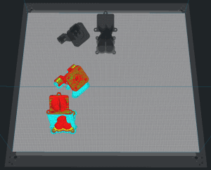
PRINT DIFFERENT MODELS IN ONE PRINT:
- Import all models
- If needed, alter settings for specific models by “Per Model Settings”
- If several models form a single part, group them together
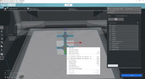
- Call “Menu→Extensions→Arrange objects for mixed mode”
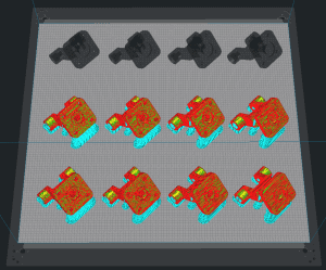
PRINT A SINGLE MODEL MULTIPLE TIMES IN ONE PRINT:
- Import the model (you can also import several models and group them together)
- Call “Menu→Extensions→Populate build plate completely” for having the maximum number of copies.
(Alternatively, you can call “Menu→Extensions→Populate build plate for sequential printing” for just populating the rows.
Or with right click on the model and “Multiply Selected Model” you can create a specific number of models and then call “Menu→Extensions→Arrange objects for mixed mode”)
Good to know:
- Always check if the order is correct in the preview.
- You can also use “Per Model Settings” for each model.
- You can group or merge several models to one “part”.
There are some additional constraints that come along when you print something, and which will reduce the maximum possible printable size of parts.
- Z-Hops (Z Hop Height)
This will lower the print volume in z-direction. Currently, we have here a value of at most 1.6 mm. - Build Plate Adhesion (Build Plate Adhesion Type)
- “Brim” or “Skirt” are the default types and will reduce the print volume in x-direction and in y-direction. With the current defaults, this will cause a reduction of 17.6 mm each.
- In the case of “Raft”, the z-direction will be reduced, too.
- Even in the case of “None”, you may get a reduction because the prime tower has a brim by default. This must also be disabled if you want to take advantage of the entire build plate.
- Build Plate Adhesion for prime towers
- Support Expansion
- The support is printed slightly bigger for stability reasons. With the current defaults, this will cause a reduction of 0.8 mm for the x-direction and the y-direction.
- Travel Avoid Distance
This a safety distance for travel moves. A part must respect this distance with respect to the border of the plate. Current default value is 1.5 mm.
Usually, this will not cause an additional reduction because the brim/skirt will guarantee this distance. But if so, we will have a 3 mm reduction for the x/y-sizes. - Infill Wipe Distance
Currently disabled! The infill must respect this distance with respect to the border of the plate.
This will likely never cause a reduction because brim/skirt and the outer/inner wall will guarantee this distance. - Dual Extrusion
Brim/Skirt will have an extra line (of the non adhesion extruder). This is a reduction of up to 2.2 mm. A prime tower with its brim will be added, too.
You need to disable “Extruder 1” to be able to activate the “Tandem Mode”.
Than you can activate “Enable Tandem Mode” which is a “Special Modes” setting.
Important: The build plate will only be refreshed when a model is imported.